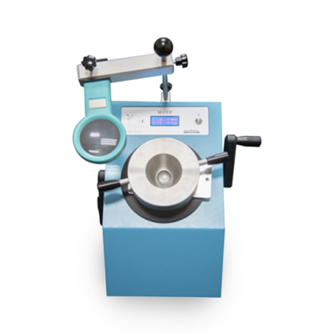
The Cupping Tester, designed with a new highly functional geared design for linear force transmission it is designed to aid user friendly testing and a magnifier to provides easy visual inspection.
A sample panel with a minimum coating thickness 0.3 mm, is clamped by an upper wheel and manually cupped by a 20 mm circumference hemispherical indenter onto to a die by a drive wheel.
The depth to cause failure is indicated on the digital display, from 0 – 10 mm, in increments of 0.01 mm.
Ⅱ. Main Technical Parameters:
| Type | TCB-II |
| Depth of Indentation | 0-10mm |
| Resolution | 0.01mm |
| Diameter of Indenter | 20mm |
| Thickness | 0.3mm-1.25mm |
| Test Panel | 70×70mm |
| Weight | 24KG |
Ⅲ. Test Procedure :
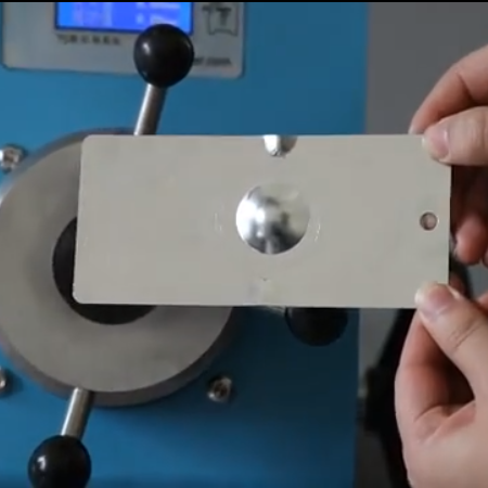
Hold the test panel firmly between the retaining ring and the die with the coating towards the die and with the hemispherical end of the indenter in contact with the test panel (zero position of the indenter).
Adjust the panel until the central axis of the indenter intersects the panel.
Advance the hemispherical end of the indenter into the test piece at a constant rate until the specified depth is reached i.e. until the indenter has travelled this distance from the zero position.
Using normal corrected vision or, by agreement, a magnifier, examine the coating of the test panel for cracking and/or detachment from the substrate.
When removing the test panel, first slacken the indenter hand-wheel to relieve pressure, then unscrew the upper clamping wheel to free the panel.


